Product Overview
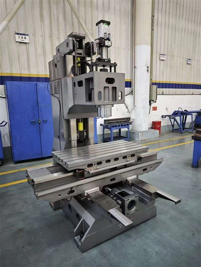
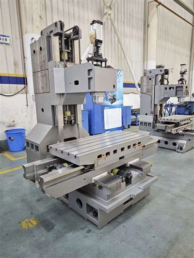
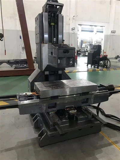
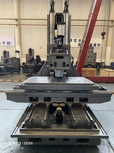
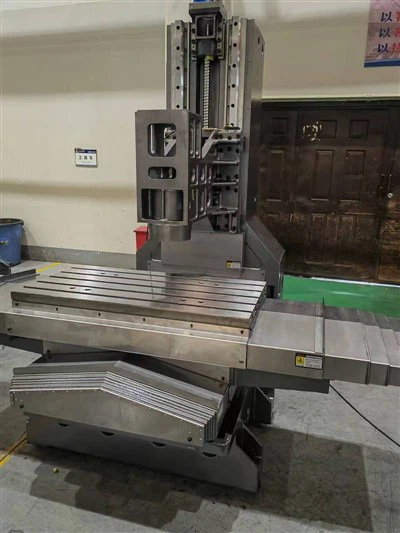
The Bridge Machining Center is engineered for heavy-duty, high-precision machining of oversized workpieces. Featuring a rigid bridge frame configuration, this machine limits deflection under high cutting loads, ensuring dimensional stability across continuous multi-axis operations. It serves primary applications in aerospace structural components, large automotive stamping dies, energy equipment housings, and heavy industrial machinery parts.
Unlike standard C-frame vertical mills, the symmetrical gantry architecture distributes thermal and mechanical loads evenly across dual Y-axis drives. This setup maintains consistent geometric tolerances when executing deep-pocket milling, high-feed roughing, and fine-finish contouring on titanium, steel, and high-strength aluminum alloys.
-
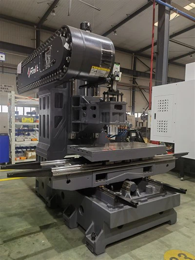
![Double Column Bridge Machine Frame]() Double Column Bridge Machine FrameFeaturing a fixed gantry structure (dual columns + fixed crossbeam), the machine ensures exceptional geometric stability. The spindle system (Y/Z axes) remains stationary relative to the foundation,

Machine Structure & Configuration
Bed and Column Casting
High-density gray cast iron subjected to stress-relieving thermal annealing and vibration aging to eliminate internal residual stresses. Ribbed structural design provides high torsional rigidity.
01
Drive System
Dual-motor synchronous rack-and-pinion or preloaded high-precision ball screws on the Y-axis (gantry movement), paired with heavy-duty linear roller guideways to minimize stick-slip effect during heavy loads.
02
Spindle Configuration
Cartridge-type or built-in motor spindles equipped with ceramic hybrid bearings, precision oil-air lubrication, and integrated fluid chiller units to control thermal growth.
03
Tool Management
Automatic Tool Changer (ATC) ranging from 24 to 60 stations (chain-type), featuring random tool selection and a tool-to-tool change time under 5 seconds.
04
Chip Evacuation
Dual-auger troughs integrated directly into the bed casting, combined with a continuous-mesh hinged chain conveyor and external high-pressure coolant flushing to prevent chip accumulation.
05
Key Features
Thermal Symmetry
Finite Element Analysis (FEA)-optimized structural layouts minimize thermal distortion along the Z-axis ram during prolonged operational shifts.
Dynamic Torque Delivery
High-torque spindle options deliver optimal material removal rates (MRR) in low-RPM roughing phases while supporting high-RPM finishing on hardened tool steels.
Real-time Compensation
Advanced CNC control packages integrate volumetric compensation models, correcting geometric errors caused by axis sag and ambient temperature shifts in real time.
Rigid Ram Design
Square-ram or octagonal-ram configuration with hydraulic counterbalancing, eliminating tool chatter during extended overhang operations.
Materials & Construction
Structural Elements:
Main structural castings are produced with controlled metallurgical formulas, featuring wall thicknesses ranging from 30mm to 80mm with internal web reinforcement to absorb harmonic frequencies generated during interrupted cuts.
Guideways & Transmission
Hardened alloy steel linear roller guides offer higher contact stiffness than ball-type guides, supporting high table loads without micro-deformation. Preloaded double-nut ballscrews (C3/C5 accuracy grade) restrict mechanical backlash to minimal tolerances.
Surface Treatment
Exposed guideway mounting surfaces undergo precision hand-scraping or high-precision grinding to achieve geometric contact ratios exceeding 80 points per square inch, securing alignment accuracy prior to assembly.
Technical Specifications
|
Specification Item |
Standard Configuration (Model: BMC-2030) |
Heavy-Duty Configuration (Model: BMC-3040) |
|
X / Y / Z Axis Travel |
3,000 mm × 2,000 mm × 800 mm |
4,000 mm × 3,000 mm × 1,000 mm |
|
Table Size |
2,800 mm × 1,800 mm |
3,800 mm × 2,800 mm |
|
Max Table Load Capacity |
10,000 kg |
20,000 kg |
|
Clearance Between Columns |
2,100 mm |
3,100 mm |
|
Spindle Taper / Speed |
Standard Taper / 8,000 RPM (Gearbox) |
High-Speed Taper / 12,000 RPM (Built-in) |
|
Spindle Motor Power |
22 kW / 30 kW (Continuous / S6) |
37 kW / 45 kW (Continuous / S6) |
|
Rapid Traverse (X/Y/Z) |
20 / 20 / 15 m/min |
15 / 15 / 12 m/min |
|
Positioning Accuracy |
+/-0.008 mm / full stroke |
+/-0.010 mm / full stroke |
|
Repeatability Accuracy |
+/-0.004 mm |
+/-0.005 mm |
|
Control System |
Industrial Multi-Axis CNC Architecture |
Industrial Multi-Axis CNC Architecture |
Die & Mold Manufacturing: Producing large stamping dies for automotive body panels, forging dies, and large injection mold cavities requiring high surface finish (Ra < 0.8 um) and strict contour accuracy.
Aerospace & Defense: Machining structural ribs, wing spars, and high-strength alloy engine casing mounts where material integrity and tight geometrical tolerances are mandatory.
Energy & Power Generation: Milling wind turbine hub castings, generator housings, and heavy reactor components under continuous heavy-load conditions.
General Heavy Engineering: Processing welded steel fabrications, industrial press frames, and large gearboxes requiring multi-face machining in a single setup.

Manufacturing & Quality Control
Machining of Castings: All structural castings are finish-machined on heavy-duty floor-type boring and milling machines in a temperature-controlled environment (+/-1 deg C) to guarantee base reference plane accuracy.
Laser Interferometer Testing: Every machine undergoes linear and volumetric laser calibration (conforming to international metrology standards) to map and compensate positioning errors across all axes.
Dynamic Contour Testing: Dynamic contouring accuracy is verified using specialized telescopic ballbar systems to measure servo mismatch, reversal spikes, and squareness errors at high feed rates.
Thermal Run Test: Spindles run continuously at maximum rated RPM prior to factory acceptance, with thermal sensor arrays monitoring bearing housing temperatures to ensure stability thresholds are met.
OEM & Customization
Specialized Heads
Optional universal indexing heads (A/C axis manual or automatic clamping), extension heads, and right-angle milling heads for multi-sided machining in a single clamping.
Workholding Integration
Tailored T-slot layouts, hydraulic clamping fixtures, zero-point clamping systems, and integrated rotary tables for multi-axis integration.
Automation Interfaces
Pre-wiring and mechanical interfacing for pallet exchange systems, robotic loading cells, and automatic workpiece measuring probes.
Chip & Coolant Customization
High-pressure through-spindle coolant systems, mist extraction units, and customized chip conveyor discharge angles to match plant layout constraints.
FAQ
As one of the most professional bridge machining center machine manufacturers and suppliers in China, we also support customized service. Please rest assured to buy bulk bridge machining center machine made in China here from our factory. Contact us for more details.
bridge machining center machine, Double Column Bridge Machine Frame